Rodrigo Oliveira

Aerospace Engineering Student - Maker - Trombonist - Plane Nerd
|
|
|
|
|
(Work in progress) Mechanical Calculator with Lego-like Modular Logic Gates
14 May 2020 -
Concept
Some weeks ago I was following my usual Youtube routine and I came across a really cool video by Ben Eater about adder circuits. n the video, Ben made one 4 bit adder with commercial logic gate ICs and that got me thinking: what if I could make mechanical logic gates and connect them together so that I could add something like 2 four bit numbers?
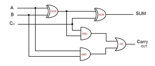
A 1 bit full adder circuit. Below, you can see the truth table for each logic gate used, as well as for the whole circuit.
| BIT 1 | BIT 2 | XOR | AND | OR | FULL ADDER |
|---|---|---|---|---|---|
| 0 | 0 | 0 | 0 | 0 | 0 |
| 1 | 0 | 1 | 0 | 1 | 1 |
| 0 | 1 | 1 | 0 | 1 | 1 |
| 1 | 1 | 0 | 1 | 1 | 10 |
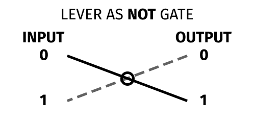
So, I obsessed a little bit about this in the following days and thought it would be really cool to have the logic gates modular, kind of like legos. They would be a small square with two inputs and one output. Inside, the logic operations would be done with levers. An example: one lever is a NOT gate, if you push one end away from you (you could call this a 1, True, Yes, etc) the other end will come close to you (0, False, No) and vice-versa.
Nowadays, with 3D printing, this idea could result in some pretty cool computing projects, so one more constraint was that each module should be easily 3D PRINTABLE so that I could share it on Thingiverse and hopefully see what crazy things people could do.
First Sketches
I spent a lot of time thinking about the mechanisms for each gate, and here are the sketches for the first mechanisms:
- OR
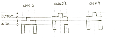
- AND
- The XOR gate is way more complicated and I have not been able to come up with a simple enough design yet. You can make one with one OR, one NAND(NOT + AND), and one AND and this might be the best solution for now.(Wikipedia)

Prototyping
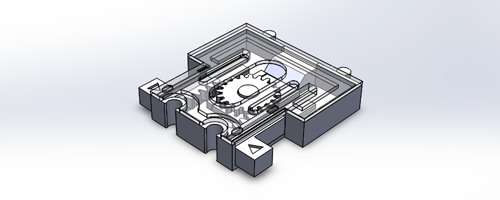
With the ideas for the mechanisms in mind, I started making a Solidworks assembly for the first gate. It was actually a NOR gate and the input bits were inverted inside by levers. Below you can see the first ever print. It is very basic, but the goal here was to get an idea of how small I could 3D print the parts and evaluate the tolerances.
With these problems fixed, it was time to address the modularity issue. This time, I designed the AND gate you can see in the cover for this post. Here is a demonstration of the modularity concept and the gate in operation.
 |
 |
Next Steps
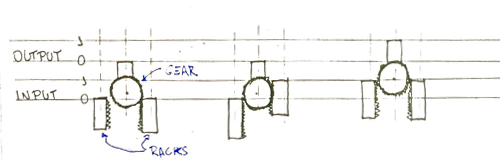
After making some of these V2.0 AND gates and trying to connect them together, I realised I had a pretty big problem, which is “backlash”. The current mechanism has gaps between the rack and the gear, and this means that if the input moves 10mm, the output will move something less than that and these gaps will sum up along the chain. Many small gaps will result in a big one in the end, and this is inherent to the design. It would have no gap if the gears had infinite teeth.
To solve this, I believe a new design is necessary. I believe the best option is using marbles and thats because they will already have the energy stored (potential) and each input will be just enough to harvest it.